Tuesday 8 November 2022

New Project - Reprogramming/fixing a Smart WiFi Socket

Following on from discussions on Twitter, I think that I should do this. 

It uses Tasmota devices and MQTT  to show what is using power when. 

An excellent writeup  by @Brunty in his blog:  https://brunty.me/post/energy-monitoring-2022-edition/

To start I need some Tasmota devices. They ain't cheap.

Can I convert my TUYA Smart devices to Tasmota. @Andysc says I can. Will I still be able to control them to turn TV ON & off at specified times automatically? 

There is Tasmotrol, but it is written by a person (Yvonne Joh) who I don't know anything about. Does it feed stuff back to China like TUYA Smart? 

I will need a home Server running 24/7, and at the moment all I have is a few spare black tower PC's. 

Can I find a small unit that plugs into a mains socket and will support some storage?   Looked for 'PC in a plug' and found some references to things like Sheevaplug, but they all seem to have ceased. 

I'll have to get a Raspberry Pi to fit into my dead Humax box when they are available. 

Suggestion that I should look at Balena_io and MING. I might have to learn some more programming if I went that route. 

Keep thinking about it.  Have discovered that Enphase uses MQTT, but I think that this is in old versions of the software. Good if it still does.  How can I test it?

21 Nov. 22

Going to flash one of my TUYA smartplugs with Tasmotrol.

The device is a https://expo.tuya.com/product/627497  model J2-SU-E16

Following https://www.superhouse.tv/44-over-the-air-tasmota-conversion-with-tuya-convert/

Setting up Rasberry Pi (10) 

It has flashed, Not sure if it was successful. 

When plugged in, no light. But Wifi Network tasmota_02AC61-3169

MAC address 12:e9:be:e7:26:65


Have left a comment on the superhouse web page.

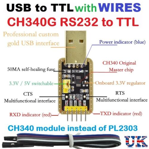
26 Nov 22. Have taken it apart and discovered that the chip in it is a common Popular one ESP-12S, and have unsoldered it from the unit. Have ordered a USB to TTL serial interface board so that I can program it. 

Best link that I have found is: 

https://templates.blakadder.com/ESP-12.html

This one has videos of programming them. 

https://www.hackster.io/brian-lough/3-simple-ways-of-programming-an-esp8266-12x-module-c514ee


29 March 2023 looking at this to make it simple:

https://www.youtube.com/watch?v=8yxEgYvoHY0

I have now found tasmotizer:

-- peterm@peterm-MBB-34204H:~$ find -name "*tasmotizer*"
-- ./.local/bin/__pycache__/tasmotizer.cpython-38.pyc
-- ./.local/bin/__pycache__/tasmotizer.cpython-310.pyc
-- ./.local/bin/tasmotizer.py
-- ./.local/lib/python3.10/site-packages/__pycache__/tasmotizer_esptool.cpython-310.pyc
-- ./.local/lib/python3.10/site-packages/__pycache__/tasmotizer.cpython-310.pyc
-- ./.local/lib/python3.10/site-packages/tasmotizer-1.2.1.dist-info
-- ./.local/lib/python3.10/site-packages/tasmotizer_esptool.py
-- ./.local/lib/python3.10/site-packages/tasmotizer.py
-- ./.local/lib/python3.8/site-packages/__pycache__/tasmotizer.cpython-38.pyc
-- ./.local/lib/python3.8/site-packages/__pycache__/tasmotizer_esptool.cpython-38.pyc
-- ./.local/lib/python3.8/site-packages/tasmotizer-1.2.1.dist-info
-- ./.local/lib/python3.8/site-packages/tasmotizer_esptool.py
-- ./.local/lib/python3.8/site-packages/tasmotizer.py

But it won't run because it is missing some bits

following instructions to install tasmota from web i/f But it cannot find USB serial port. 

https://tasmota.github.io/docs/Getting-Started/#needed-software

Web:  https://tasmota.github.io/install/

Have downloaded basic Tasmota from http://ota.tasmota.com/tasmota/release/

This nearly works with the TTL-USB dongle that Ben gave me. It didn't react with Mine. 

Here is another story about step-by-step programming a device with Tasmota.

https://blog.horner.tj/emporia-smart-plugs-tasmota/

This tells how to set Bootloader mode on GPIO15 (pin10)

https://docs.espressif.com/projects/esptool/en/latest/esp8266/advanced-topics/boot-mode-selection.html

7 April 2023.

So I need GPIO-15 Pulled low to enable flashing. This is the pin next to GND. 

SUCCESS!

Following a hint online:

sudo apt-get install python3-pyqt5.qtserialport

and now this works:

 python3 ./.local/lib/python3.8/site-packages/tasmotizer.py
and brings up tasmotizer. 

But I need to find the config file. 

On TAsmotizer, just click the little box for the section that you want to config, so I did and added the Wifi credentials, and then 'saved' this config, which sent it to the device.   Fing found it, but the tasmotizer tablet app didn't. I think I need to set up a tasmotizer web server for this, which probably means using a Raspberry Pi. 

Correction: Fing did not find it. and searching for a WIFI connection to it found nothing either. 

Wrote to Horner re my problems

Hi, as suggested in your blog on this, I am asking for the benefit of your experience. I have an unbranded Smart Switch with TUYA software. It is very similar to the Lombex unit: https://templates.blakadder.com/lombex_U11.html.   I have removed the ESP12 microprocessor and connected it to my Kubuntu computer, and have been able to flash it using 

https://tasmota.github.io/install/   It was necessary to connect both GPIO-15 and GPIO-0 to 
ground to get it to flash. and then have started Tasmotrol to configure it, which seems to work. 
I then tried to send the generic module configuration, and that transferred. The problem is that the 
device never appears in my wireless network  - testing with fing on my tablet. 

Not sure what other info I can give you to help. Attached is a picture of the connection.
 
The ESP-12S came out of the slot on the main board of the unit. 

Any thoughts appreciated,
------------------- ---------------- ------------
another similar plug:
https://templates.blakadder.com/silentnight_485418G.html 

with a comment that  New Tuya devices have replaced their Wi-Fi module with one incompatible 

with Tasmota!!!

10/4/23 Likely conclusion: None of the Tasmota buolds loaded  have had wireless working, so my 

supposition is that Tuya are using an ESP-12 in this device that uses the Realtek wifi drivers rather 

than their original ones. 

I am going to test this hypothesis using these three links:

1]  https://www.instructables.com/Getting-Started-with-the-ESP8266-ESP-12

2]  https://www.instructables.com/ESP-12E-ESP8266-With-Arduino-Uno-Getting-Connected/

3]  https://circuitjournal.com/programming-esp8266-over-wifi

This one 3] is about working with these variants ESP-12E / ESP-12F / NodeMCU so I'll leave it for now. 

2] is about an 8266 E and builds on 1] so I'll start there. 

It has a warning about not using the 3V3 from the USB-TTL adapter as it doesn't supply enough power. 

I cannot get the Arduino IDE serial monitor to  show anything. 

Trying to get an Arduino program working for the ESP8266, and I just get this error:

"module 'time' has no attribute 'time_ns'" in /tools/mkbuildoptglobals.py  and can't find a cure. Something to 

do with the version of Python perhaps. 


16/4/23  Interesting teardown of a couple of smart plugs:

https://www.hackster.io/news/teardown-of-a-smart-plug-or-two-6462bd2f275b

The TCP-Smart plug that I have  contains this:

https://developer.tuya.com/en/docs/iot/wb2s-module-datasheet?id=K9ghecl7kc479

and looks like this. 


2023-05-19

Discovered a new article about programming an ESP-12 with Tasmota

https://www.elektroda.com/rtvforum/topic3816654.html

It implies that the  WB2S in the TCP switch has to be replaced with an ESP-12 device.


Tuesday 1 November 2022

Second try at CTC DIY 3D printer Z-axis wobble fix

25/3/2023 Don't bother reading this. I gave up when I never could communicate via the Arduino to the ANET board.

-------------- ------------------- -------------- --------------- 


I am going to try and start again. 

I think that I have prepared the Arduino Uno for use as a downloading tool.

I now need to find the Library/Hardware data for this ANET  V1.5.

Basic configuration:

/Home/peterm/Arduino/arduino-ide_nightly-20221020_Linux_64bit.AppImage

/Home/peterm/Arduino/Hardware/anet

/Home/peterm/Arduino/libraries

/Home/peterm/Arduino/Marlin-2.1.1

Set Preferences Additional Board Manager to https://mcudude.github.io/MightyCore/package_MCUdude_MightyCore_index.json

 And installed in Boards Manager the MightyCore.

Then in Boards Manager I was able to select ATMega1284 which is what this ANET card has. 

I think that I have to load some additional Configuration files from somewhere to select the file for my ANET board. Need to look that up again. 

Found that here: https://github.com/MarlinFirmware/Configurations

Following along from this, with modifications.

https://www.youtube.com/watch?v=38PkynA1uGI&t=157s   at 3:00 in

His file links:     * Software links

Marlin firmware https://github.com/MarlinFirmware/Marlin Marlin Default Configuration Files https://github.com/MarlinFirmware/Con...

from 5  minutes in, he wants you to download Visual Studio. It is available for linux. 
https://visualstudio.microsoft.com

Just after 8:00 mins he refers to another link in order to get the bootloader onto the  ANET board. I may have to do this first. 

------------ ----------- ------------ -----------
2022-11-04
Going back a step to get the bootloader in. 
https://www.youtube.com/watch?v=RQIizXtf9oo&t=0s

This also does the MArlin firmware to the printer, after getting the bootloader in. 
3:10 Arduino as Programmer to 4:40
4:45 wiring to ANET board
5:30 Burning bootloader
6:10  burning MArlin firmware to board. 


at 5:42 cannot find the ANET  optiboot in the boards manager. 
from the comments:
Arduino 1.8.5 it didn't have the anet boards listed. I found how to add those at https://github.com/SkyNet3D/anet-board. [ 2023/7/14 This link has disappeared]
Followed these instructions, but I had already done them, but the IDE does not seem to find the hardware folder.

BAH: Its a known fault: https://forum.arduino.cc/t/hardware-folder/699133

------------ -------------- -------------- ----------
2022-11-06
- removing Arduino IDE 2  Appimage
- removing /Hardware directory
- removing /Library directory

Download Arduino IDE 1.8.19  https://www.arduino.cc/en/software
There is a link to the installation instructions
Open console, run sudo sh install.sh
Now to find Hardware folder. 

OK, it's in /Arduino/Hardware and I have added the ANET stuff. 


2022-11-28 
It looks like the Marlin firmware compiles /verifies Ok with the MightyCore  Atmega chip specified, but it won't download via the Arduino. I will have to rewatch the video.  

2022-12-01
IT verifies and tries to load only if the capacitor to the reset pin is not connected to ground.  

error message:

avrdude: Expected signature for ATmega1284P is 1E 97 05

Double check chip, or use -F to override this check.


Two things I have learnt today. 


Folder /peterm/Arduino/hardware must have a lower case h on hardware. 

Putting the Anet folder from /home/peterm/3D_Printing/CTC-Prusa-i3-Pro-B-Anet-board  

into the hardware  folder means that Arduino IDE finds the ANET boards. 


This does Verify, but doesn't download because of 

Arduino: 1.8.19 (Linux), Board: "Anet V1.0"


Sketch uses 54624 bytes (43%) of program storage space. Maximum is 126976 bytes.

Global variables use 2475 bytes of dynamic memory.

avrdude: stk500_getsync() attempt 1 of 10: not in sync: resp=0x1c

avrdude: stk500_getsync() attempt 2 of 10: not in sync: resp=0x1c

avrdude: stk500_getsync() attempt 3 of 10: not in sync: resp=0x1c

avrdude: stk500_getsync() attempt 4 of 10: not in sync: resp=0x1c

avrdude: stk500_getsync() attempt 5 of 10: not in sync: resp=0x1c

avrdude: stk500_getsync() attempt 6 of 10: not in sync: resp=0x1c

avrdude: stk500_getsync() attempt 7 of 10: not in sync: resp=0x1c

avrdude: stk500_getsync() attempt 8 of 10: not in sync: resp=0x1c

avrdude: stk500_getsync() attempt 9 of 10: not in sync: resp=0x1c

avrdude: stk500_getsync() attempt 10 of 10: not in sync: resp=0x1c

An error occurred while uploading the sketch


This report would have more information with

"Show verbose output during compilation"

option enabled in File -> Preferences.


So I need to find out how to get it in sync.

I had the connector to the ANET board in the wrong position (one set of pins down from where it should be.) When I put it in the right place I fried the UNO.

Thought: I had the MISO/MOSI pins in the wrong places. 

-------------- -----------
Now to try using the special card that I bought. 
referring back to this:
https://www.youtube.com/watch?v=oZVTYpHnpIw  

I somehow need to determine the use of the pins on this USB to TTL device.

One reference: 
https://support.th3dstudio.com/helpcenter/anet-bootloader-flashing-guide-usbasp/


Another useful site for Arduino, but no help with my current problem

https://www.circuito.io/blog/arduino-uno-pinout/


I will try TX to MISO, and RX to MOSI
TX is Blue to pin 3, 
GND is Grey to pin 8
and RX is purple to pin 6

6/12/2022  Discussion at DLUG Meeting. to use MISO/MOSI i use a JTAG protocol.
I will be sent some information. 


22/12/22 
Some links found by Ben
https://www.thingiverse.com/groups/anet-a8-prusa-i3/forums/general/topic:33728


https://anet3d.com/blogs/download/open-source-firmware-of-a8


14/1/23  
After blowing up the Arduino Uno,
I am preparing another with an ICSP cable as per this:

https://www.instructables.com/Arduino-ICSP-Programming-Cable/


Summary:
Bootloader is downloaded to Arduino UNO.
Cable as above connects to ANET board. 
Marlin 2 Firmware compiles
MArlin firmware fails to download to board with error 
 -    avrdude: stk500_getsync() attempt 1 of 10: not in sync: resp=0x00
and I don't know which item is not in sync. 

Question. Is the fact that  the Arduino is connected to the ANET board via the ICSP connections inhibiting the connection? 

Question 2: I have uploaded the AVRISP firmware to the arduino to act as the bootloader for the ANET board, but is the next step to use this to upload a bootloader to the ANET board and then use that to upload the Marlin Firmware?   I'll have to review one of the videos. 

2023/1/18 Discovered an error in creating that cable. I should disconnect the +v line so that the Arduino is not getting power from both the USB and the destination card.  I will replace the pin with a dummy one.   And another. The -ve side of the capacitor was connected to the grey (MOSI) wire, not the white ground wire. I blame that on the poor lighting. 

2023-1-20   Created a straight through  5 pin cable with a dummy pin holder where the +V is labelled.
It 'nearly' worked. I have seen this error before. 
"avrdude: Yikes!  Invalid device signature.
         Double check connections and try again, or use -F to override
An error occurred while uploading the sketch
         this check."

I need to find this previous occurrence and see what I can do.  It wasn't far back, but didn't give me a solution.
I notice that the screen is flashing alternate lines. 

One solution suggested was to use a capacitor on the reset pin, As I have tried. 
Another was to reduce the version of the AVR tools to 1.6.9. That had exactly the same error so I reverted to the highest version. 

I might look at the software for the  device signature. 

Tried to burn a bootloader. Got error:
"Error while burning bootloader.
Reading | ################################################## | 100% 0.02s

avrdude: Device signature = 0x000000
avrdude: Yikes!  Invalid device signature.
         Double check connections and try again, or use -F to override   this check.  "

Not quite sure where to report this in order to ask for help.

23/1/2023
Removed the Reset line from the ICSP and connected it to pin 10. 

Then set  it up and got this error:
"avrdude: Expected signature for ATmega1284P is 1E 97 05
         Double check chip, or use -F to override this check.
Wrong microcontroller found.  Did you select the right board from the Tools > Board menu?"

Seen this before. 

But, it's RTFM time. I found this:
https://docs.arduino.cc/built-in-examples/arduino-isp/ArduinoISP
and at one point it says:
Going through the lines of the sketch you find a number of parameters that need to be set according to the target board. These parameters are, however, set by a specific file available for each bootloader/board supported by the Arduino Software (IDE). 

So do I need to edit this file?   No, I don't think so.


24/1/2023   I swapped the lines  MISO/MOSI  so that they are a crossover cable , but got the same error.

Looking around  for ways to read the signature for my ANET I found this: 

https://arduino.stackexchange.com/questions/23751/using-arduino-uno-to-retrieve-atmega328p-pu-chip-signature

https://www.instructables.com/How-to-Fix-Expected-Signature-for-ATMEGA328P-Is-1E/


20/3/2023  Had a thought about whether I could use my USB to TTL adapters to program the ANET card. The answer is NO. They do not support I2C communications. No clock line. 

Continue with Arduino UNO. 

ANET                                                                               UNO


o                      o                                                      o                    o
                                                            (violet)    MISO             VCC


o                      o                                                      o                    o
GND             Reset                              (black)    SCK      (blue) MOSI
(grey)            (brown

o                      o                                                      o                    o
MOSI            SCK                                              RESET      (grey) GND
(violet)          (black

o                      o                                                      
VCC              MISO
N/C                (blue)

o                      o                                                      

------------------------- ------------------------ -------------------


Today I am thinking of working through this to put a bootloader onto the ANET board. 
https://www.thingiverse.com/thing:4462696

see other blogs
-------------------------

6 October 2023
Bought  a metre long M8 threaded rod from Jewsons and cut it into 3. Replaced riser rods with these in other universal joints. It still wobbled. It is to do with the motors and connection to the rods - needs thought.