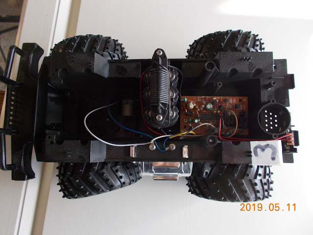
I'll give it a go with SD card #7, which has the AP built in and see if that is any better.
- 2019-06-13 Car number 2 with R-Pi3W and Card#7 out on the road, it works aside from the fact that left and right are wrong way around, just not very fast to respond. Is it worth doing a video showing it?
- How can I improve response times?
----------------------------
Because of the things that I have found out about pwm for driving the RC airplane servo's I might try and make the forward/back work using pwm with every press of the 'forward' button adding 5% to the pwm pulsewidth.
At the moment struggling to get basic pwm operation working in the program instead of go/stop.
---------------------------
9/9/2019
I did get this working. One of the things about PWM is that driving Remote Control Servos
uses PWM of about 1.5% to 2.5% ( these are just approx figures from my mind, check elsewhere for actual limits) To drive the car motors I noticed that it didn't do anything at 5% PWM, so I made it increase in steps of 15% and this worked fine. Another challenge was getting the feedback to display in the HTML the figure of the PWM value.
Here is the python code for the car: [some comments removed]
from flask import Flask, render_template
# This gives us control of the Raspberry Pi's pins.
import RPi.GPIO as GPIO
import time
# Tell it which pin number we'll be using to refer to the GPIO pins.
# We will use the physical pin ordering. Set initial state of pins
GPIO.setmode(GPIO.BOARD)
MotorFwd = 12
MotorBack = 16
MotorLeft = 19
MotorRight = 23
GPIO.setup(MotorFwd, GPIO.OUT)
GPIO.setup(MotorBack, GPIO.OUT)
GPIO.setup(MotorLeft, GPIO.OUT)
GPIO.setup(MotorRight, GPIO.OUT)
# PWM pin
u_d_pin_no = 18
GPIO.setup(u_d_pin_no, GPIO.OUT)
frequency_hertz = 50
pwm = GPIO.PWM(u_d_pin_no, frequency_hertz)
PWM_Stop = 0
PWM_value = 0
PWM_increment = 3
# becomes 15 after calculations
# total number of milliseconds in a a cycle. Given this, we will then
# know both how long we want to pulse in this cycle and how long tghe
# cycle itself is. That is all we need to calculate a duty cycle as
# a percentage.
ms_per_cycle = 1000 / frequency_hertz
# now lets get into Flask
app = Flask(__name__)
@app.route('/')
def index():
return render_template('index.html')
@app.route('/motor-stop/')
def on():
# motor.stop()
PWM_value = 0
duty_cycle_percentage = PWM_value
# print("Duty Cycle[S]: " + str(duty_cycle_percentage))
pwm.start(duty_cycle_percentage)
return render_template('index.html')
@app.route('/up_15/')
def up_15():
global PWM_value
PWM_value = PWM_value + PWM_increment
duty_cycle_percentage = PWM_value * 100 / ms_per_cycle
# print("Duty Cycle[F]: " + str(duty_cycle_percentage))
pwm.start(duty_cycle_percentage)
# time.sleep(.5)
# pwm.ChangeDutyCycle(0)
return render_template('index.html', PWM_PC = duty_cycle_percentage)
@app.route('/down_15/')
def down_15():
global PWM_value
if (PWM_value > 0) :
PWM_value = PWM_value - PWM_increment
duty_cycle_percentage = PWM_value * 100 / ms_per_cycle
# print("Duty Cycle[F]: " + str(duty_cycle_percentage))
pwm.start(duty_cycle_percentage)
# time.sleep(.5)
# pwm.ChangeDutyCycle(0)
# endif
return render_template('index.html')
@app.route('/motor-left/')
def motorleft():
GPIO.output(MotorLeft,GPIO.HIGH)
GPIO.output(MotorRight, GPIO.LOW)
time.sleep(1)
GPIO.output(MotorLeft, GPIO.LOW)
return render_template('index.html')
@app.route('/motor-right/')
def motorright():
GPIO.output(MotorLeft, GPIO.LOW)
GPIO.output(MotorRight, GPIO.HIGH)
time.sleep(1)
GPIO.output(MotorRight, GPIO.LOW)
return render_template('index.html')
if __name__ == '__main__':
app.run(debug=True, host='0.0.0.0')
# We have shut all our stuff down but we should do a complete
# close on all GPIO stuff. There's only one copy of real hardware.
# We need to be polite and put it back the way we found it.
pwm.stop()
GPIO.cleanup()
Having done all this I decided to do an R/C boat as it would combine the motor drive and the servo drive. I have given up on this idea because 1] I don't have a boat 2] the little motor that I was going to use didn't work with PWM and 3] I don't have a propellor.


