As our Humax 9150T DVRs are exhibiting some funny characterisitics, I thought that I would see what I could do with my Raspberry Pi. At the DLUG computer club the other night, Kodi was suggested as probably the best software for this. https://kodi.wiki/view/HOW-TO:Install_Kodi_on_Raspberry_Pi
Ia getting together the bits. I was going to use my 160GB Sata Hard disk, but I don't have a USB converter for it. I am going to use a 40GB IDE disk with my IDE to USB converter. I have my freecom DVB TV stick if that can be used, and the R-Pi bodel B is available, or maybe the Pi-zeroW. I have a seven port USB hub which may be up to the job - That we will see.
Step one - download the software and get it working.
Initially it wouldn't connect by Ethernet, so I started it on WiFi and it connected. I have updated and upgraded the Raspian Buster system, and now am installing Kodi.
Have attached 40G IDE disk via USB, and restarted R-Pi.
From Kodi Wiki page, I cannot find if I can run Kodi via SSH. It seems to want a big screen and a remote control for all operations.
It's not simple - I can't be bothered.
Wednesday, 4 December 2019
Sunday, 15 September 2019
Upgrading an Android OS
My Argos Bush android tablet is running Android 6.0 which is Build Number MRA58K@ARCHOS.20160617.013735.Catalpa.
I have recently tried to install a couple of Apps and been told that they were not compatible with my tablet.
Can I rebuild a later Android OS for my tablet? 15/9/2019
The Archos site is no use: https://www.archos.com/gb/support/downloads.html?type=tab
https://www.androidauthority.com/build-custom-android-rom-720453/
The two things that I would need help obtaining:
https://www.youtube.com/watch?v=99LUjX63LhU
https://www.youtube.com/watch?v=1pAr5VzpxyY
17/9/19 emailed Archos:
This Android Tablet is running Android 6.0 and I am now finding Apps that won't run on it. How can I upgrade it to a higher version of Android?
I am happy to try and build the OS myself if given the source and binaries neede, and possibly some instruction.
This would lead to the question - How to export/backup the current OS before attempting any updates, in case of failure.
Thank You, Peter Merchant
21/9/19 No response from them yet, but look what I found:
https://source.android.com/
This will be quite a learning experience
2/10/19 Suggestion from LUG www.xda-developers.com which is on topic but only seems to cater for popular devices.
I have recently tried to install a couple of Apps and been told that they were not compatible with my tablet.
Can I rebuild a later Android OS for my tablet? 15/9/2019
The Archos site is no use: https://www.archos.com/gb/support/downloads.html?type=tab
https://www.androidauthority.com/build-custom-android-rom-720453/
The two things that I would need help obtaining:
Grab the source – This is an easy step, however it takes a long time. For me it took over 24 hours. Such a large download only happens once, further syncing with the main source tree will be incremental.
Obtain proprietary binaries – The binary drivers should be unpacked in your working directory.
https://www.youtube.com/watch?v=99LUjX63LhU
https://www.youtube.com/watch?v=1pAr5VzpxyY
17/9/19 emailed Archos:
This Android Tablet is running Android 6.0 and I am now finding Apps that won't run on it. How can I upgrade it to a higher version of Android?
I am happy to try and build the OS myself if given the source and binaries neede, and possibly some instruction.
This would lead to the question - How to export/backup the current OS before attempting any updates, in case of failure.
Thank You, Peter Merchant
21/9/19 No response from them yet, but look what I found:
https://source.android.com/
This will be quite a learning experience
2/10/19 Suggestion from LUG www.xda-developers.com which is on topic but only seems to cater for popular devices.
Saturday, 14 September 2019
Build your own Electric car
If I wanted to build my own car, real not toy, where would I start?
What components would I need? I would probably like to start with an old mini, because it is small and light.
Recently I have seen this new motor design:
https://www.youtube.com/watch?v=8gO60bt6rqk&feature=youtu.be
But in the past I saw a mini with individual motors in each wheel which I liked.
https://www.treehugger.com/cars/electric-mini-0-60-in-4-seconds-it-has-motors-in-its-wheels.html
It might have used these:
https://www.proteanelectric.com/
You need power for the motors, and a power control system,. You also need all sorts of computers to feed information to the driver, look after safety details, and react to the driver to perform operations on the car, such as signalling. Do these computers need a seperate power source?
As with anything you also need a braking system.
More thoughts to be posted as they arrive, and then I'll sort them and rewrite this.
Other people have already done this:
https://www.instructables.com/id/Build-your-own-Electric-Car/
https://www.designboom.com/technology/low-cost-diy-electric-car-made-from-recycled-parts-380-mile-range-06-17-2017/
25/10/2019 On BBC. It mentions Protean (above)
https://www.bbc.co.uk/news/business-49958457
Saturday, 31 August 2019
Preparing SD cards for Raspberry Pi
Step by Step instructions on how I do it.
First use Etcher to download the program to the SD card. Today this is Raspbian Buster.
Use the browser to connect to the Boot partition of the SD card and create an empty file called 'ssh'
Now plug the SD card into the R-Pi and power it on. Connect via Ethernet. Use a utility like fing on a tablet to determine the IP address.
We need to configure networking. I have three files on my PC that are copies of the networking files from the R-Pi that are set up the way that I like them. I use a fixed wireless and a fixed Wired ethernet address on my devices.
The IP address found by fing is 192.168.1.22. In a terminal, use ssh to connect to the R-Pi.
ssh -l pi 192.168.1.22. I always have to reset keygen when I am operating on a different IP address here.
cd ..
cd ..
cd etc
sudo nano dhcpcd.conf and toward the end of the file add the lines:
# Example static IP configuration:
interface eth0
static ip_address=192.168.1.9/27
static routers=192.168.1.1
static domain_name_servers=192.168.011 8.8.8.8
interface wlan0
static ip_address=192.168.1.8/27
static routers=192.168.1.1
static domain_name_servers=192.168.1.1 8.8.8.8
Comment out the line "slaac private"
CTRL o to write file and CTRL x to exit
cd wpa_supplicant
sudo nano wpa_supplicant.conf
change this file to be:
ctrl_interface=DIR=/var/run/wpa_supplicant GROUP=netdev
update_config=1
country=GB
network={
ssid="bmth-wireless"
psk="3C0M5PGM"
# proto=RSN
key_mgmt=WPA-PSK
# pairwise=TKIP
# auth_alg=OPEN
}
Save and exit
Don't forget to change the ESSID and PSK to your own values.
I had to change the properties of this file so that it was accessible.
sudo chmod 777 wpa_supplicant.conf.
Now other Raspberry pi preparations and setup
Use sudo raspi-config to expand the file system (Under advanced settings).
sudo apt-get update
At this point I reboot to get the new IP addresses. You will need to ssh in again.
sudo apt-get install python3-flask.
mkdir rc-car
cd rc-car
mkdir templates
save app.py in the rc-car directory
save index.html in the templates directory
Use filezilla and transfer files to the Pi or copy and paste contents of files using nano.
Need a script file to start Flask. It is in the /pi directory go-car.scr
It is:
First use Etcher to download the program to the SD card. Today this is Raspbian Buster.
Use the browser to connect to the Boot partition of the SD card and create an empty file called 'ssh'
Now plug the SD card into the R-Pi and power it on. Connect via Ethernet. Use a utility like fing on a tablet to determine the IP address.
We need to configure networking. I have three files on my PC that are copies of the networking files from the R-Pi that are set up the way that I like them. I use a fixed wireless and a fixed Wired ethernet address on my devices.
The IP address found by fing is 192.168.1.22. In a terminal, use ssh to connect to the R-Pi.
ssh -l pi 192.168.1.22. I always have to reset keygen when I am operating on a different IP address here.
cd ..
cd ..
cd etc
sudo nano dhcpcd.conf and toward the end of the file add the lines:
# Example static IP configuration:
interface eth0
static ip_address=192.168.1.9/27
static routers=192.168.1.1
static domain_name_servers=192.168.011 8.8.8.8
interface wlan0
static ip_address=192.168.1.8/27
static routers=192.168.1.1
static domain_name_servers=192.168.1.1 8.8.8.8
This may vary depending on your network and Sub-network mask.
Comment out the line "slaac private"
CTRL o to write file and CTRL x to exit
cd wpa_supplicant
sudo nano wpa_supplicant.conf
change this file to be:
ctrl_interface=DIR=/var/run/wpa_supplicant GROUP=netdev
update_config=1
country=GB
network={
ssid="bmth-wireless"
psk="3C0M5PGM"
# proto=RSN
key_mgmt=WPA-PSK
# pairwise=TKIP
# auth_alg=OPEN
}
Save and exit
Don't forget to change the ESSID and PSK to your own values.
I had to change the properties of this file so that it was accessible.
sudo chmod 777 wpa_supplicant.conf.
Now other Raspberry pi preparations and setup
Use sudo raspi-config to expand the file system (Under advanced settings).
sudo apt-get update
At this point I reboot to get the new IP addresses. You will need to ssh in again.
sudo apt-get install python3-flask.
mkdir rc-car
cd rc-car
mkdir templates
save app.py in the rc-car directory
save index.html in the templates directory
sudo
apt install python3-gpiozero
Use filezilla and transfer files to the Pi or copy and paste contents of files using nano.
Need a script file to start Flask. It is in the /pi directory go-car.scr
It is:
export FLASK_APP=/home/pi/rc-car/app.py
flask run –host=192.168.1.8
sudo chmod 777 go-car.scr to make it executable.
Also edit /etc/rc.local and add these two lines to it.
Setting up Ad-Hoc networking:
If Wireless doesn't work, it is because the firmware is not installed:sudo chmod 777 go-car.scr to make it executable.
Also edit /etc/rc.local and add these two lines to it.
Setting up Ad-Hoc networking:
sudo apt-get install dnsmasq hostapd    --> done


stopped dnsmasq and hostapd, and rebooted.
got as far as installing and shutdown instead of reboot.
Changed wireless SSID to 'rc-car' and WPA to 'Ashmeads'
IP range is dhcp-range=192.168.4.2,192.168.4.20,255.255.255.0,24h
Edit /etc/dnsmasq.conf to containinterface=wlan0
dhcp-range=192.168.4.2,192.168.4.20,255.255.255.0,24h
sudo apt-get install firmware-zd1211
Sunday, 18 August 2019
8mm Film digitising
For a long time I have wanted to see what was on the two 8mm films that I have. On friday 16th August I bought a Bell and Howell 635 Moviemaster projector at the market. I haev brought it home and lubricated it, and got it working. I lost the cheat sheet showing how to thread the film when I packed it up at the market, but I have found it here:
http://www.acexie.com/bell-howell-model-635-projector/
I have picked up the manual from here though:
https://memoriesofrxmp.info/wp-content/uploads/2017/09/Product-Brochure-BH-635.pdf
It is now downloaded.
Now I think that I have heard that you have to sync the frames palying with the frames being recorded on the digital camera. That's the enxt investigateion.
Friday, 19 July 2019
Reading MRI scans
I found some old MRI scans on a memory stick and thought that I would see if I could read them. It seems that they are in Dicom format but the files are named a00001 etc.
A little research led me to a reader called Amide [insert hyperlink here] but it didn't work. I discovered that it needed a utility(?) called xmedcon. Both were available in the Kubuntu repositories. I used a different hard disk because I didn't want it affecting my main disc. I have emailed the creator via sourceforge to see if I can get any help.
Then I had another look and found a list prepared by https://people.cas.sc.edu/rorden/dicom/index.html
and downloaded his program MRIcron. this won't work directly on Dicom files but needs to convert tehm, via a program called mricroGL. This brings up a form to specify the source and destination directories and some buttons for the format, but no 'button' to make it do it. Something I pressed did it, and now I have imported it and can see the MRI results.
It identifies each 'picture' by a number between -127 and 90, but jumps about 6 between each view.
I have it running and am looking at one of the three possible viewing modes [Axial], and I see a large round tube beside the spine. This site identifies it: https://www.kenhub.com/en/library/anatomy/blood-supply-of-the-spinal-cord
Thursday, 11 July 2019
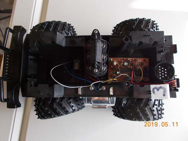
RC Car Number 3
This car has thrown a curve ball. The Receiver IC is a SM6135W and it has the same pinouts as the IC in Car 2, so I would expect the car to behave the same. But it doesn't. This is using the Flask software with the Raspberry Pi 3W configured as an Access Point.
In Car 3 Forward makes the wheels turn Left, and Backwards turns Right, And the Left/Right buttons make the car go backwards or forward for a very short time.
But the IC has the same pinouts as shown here:

Here is a picture of the driver board, with the receiver IC replaced by an IC socket


The Blue and White wires drive the steering motor, and the Yellow and Grey wires drive the main motor. The Red and Black wires are the power. On the second picture, above the grey wire is a block of 6 pinouts that the blue wire connects to and a sort of Z shaped set of pinouts where the white wire connects.
I am going to replace it with a HW-95 driver board to see if it works properly.

This has a +5 connection and a +12 connection. I don't know which to use yet.
Here is a link to it: https://www.amazon.co.uk/Neuftech-H-bridge-stepper-controller-Raspberry/dp/B01KBTNHS6/ref=pd_lpo_sbs_23_t_0?_encoding=UTF8&psc=1&refRID=4E1H9CXKZQTS0W8Y9Y9Y
A comprehensive video is here:
and another
If I can get it working basically, I might then try to use PWM to drive the motors.
2019-07-13 I have it working, but of course it is efectively an eviscerated car with the L298 motor controller driven by the Raspberry Pi. The car batteries 6x 1.5 AA cells are connected to the +5v input on the controller and the car crawls very slowly and doesn't have enough power to back up the very smallest of slopes (Driveway).
At least crawling this slowly it doesn't get away from me. Another 'feature' is that the steering wheels do not have an automatic return to zero as car #2 did.
I'll move these batteries to the +12 terminal and see if it makes a difference. RESULT: It makes a terrific difference. The car runs like it should. The next problem is what to do after it has run into something and ceases to respond. The first time this happened the power cord had pulled out of the R-Pi. I don't know what happened the next time.
2019-07-28 Here is the proof: https://www.youtube.com/watch?v=jsj-cnHkr_k&t=9s
Next is to replace the original card, but swap the steering and motive motor wires. I have a record of where they were connected on the board.
2020-01-14 New thoughts.
I have just watched a video about driving multiple Servos from a Raspberry Pi: https://www.youtube.com/watch?v=xHDT4CwjUQE
and then one about autonomous vehicles - farming implements, so it caused me to look at Autonomous vehicles driven using a Raspberry Pi so I found this:
This one uses a Servo Shield(Hat). My thoughts turned to controlling the steering using a Servo. I wish that I had not dumped Car #2 as I could have used that. It's steering was never any good.
Watch this space?
2020-06-08
Been a while.
It should be noted that this is using uSD card #7.
I have put the original driver board back in, and created brackets to hold the R-Pi ZeroW in place. It runs well, but is slow to respond. In the field with grass tufts it didn't seem to have power to get over them. Maybe I need to get an adjustable ramp and see how steep it can go? One thought here is that the outputs of the GPIO are +3 volts approx where the original receiver chip was a +9 volt system. If I had a buffer to give a greater output voltage to the driver board would it have more power, or just go faster. This is not an easy thing to implement. Documentation is confusing but suggests that IC is +5v and output is 3v, so is OK.
I discovered that the steering return to home mechanism was gone, so I created one with a paper clip and it seems to work. However the steering software only turns it for one second. I am going to increase this to two seconds.
Going up the road it is sensitive to camber and doesn't react well to being asked to steer up the camber.
The steering has now been changed to two seconds and then it has a stop command so the steering returns to zero position. Maybe I should adjust the software to have a center steering button and no time set?
Sunday, 26 May 2019
RC car improvements up to June 2019 - and a future possibility?
Car number 2 works with the software on SD card #3, but the problem is that it takes off too fast and needs a lot more room than I have to fully test it. It also doesn't respond very quickly to the tablet.
I'll give it a go with SD card #7, which has the AP built in and see if that is any better.
- 2019-06-13 Car number 2 with R-Pi3W and Card#7 out on the road, it works aside from the fact that left and right are wrong way around, just not very fast to respond. Is it worth doing a video showing it?
- How can I improve response times?
----------------------------
Because of the things that I have found out about pwm for driving the RC airplane servo's I might try and make the forward/back work using pwm with every press of the 'forward' button adding 5% to the pwm pulsewidth.
At the moment struggling to get basic pwm operation working in the program instead of go/stop.
---------------------------
9/9/2019
I did get this working. One of the things about PWM is that driving Remote Control Servos
uses PWM of about 1.5% to 2.5% ( these are just approx figures from my mind, check elsewhere for actual limits) To drive the car motors I noticed that it didn't do anything at 5% PWM, so I made it increase in steps of 15% and this worked fine. Another challenge was getting the feedback to display in the HTML the figure of the PWM value.
Here is the python code for the car: [some comments removed]
from flask import Flask, render_template
# This gives us control of the Raspberry Pi's pins.
import RPi.GPIO as GPIO
import time
# Tell it which pin number we'll be using to refer to the GPIO pins.
# We will use the physical pin ordering. Set initial state of pins
GPIO.setmode(GPIO.BOARD)
MotorFwd = 12
MotorBack = 16
MotorLeft = 19
MotorRight = 23
GPIO.setup(MotorFwd, GPIO.OUT)
GPIO.setup(MotorBack, GPIO.OUT)
GPIO.setup(MotorLeft, GPIO.OUT)
GPIO.setup(MotorRight, GPIO.OUT)
# PWM pin
u_d_pin_no = 18
GPIO.setup(u_d_pin_no, GPIO.OUT)
frequency_hertz = 50
pwm = GPIO.PWM(u_d_pin_no, frequency_hertz)
PWM_Stop = 0
PWM_value = 0
PWM_increment = 3
# becomes 15 after calculations
# total number of milliseconds in a a cycle. Given this, we will then
# know both how long we want to pulse in this cycle and how long tghe
# cycle itself is. That is all we need to calculate a duty cycle as
# a percentage.
ms_per_cycle = 1000 / frequency_hertz
# now lets get into Flask
app = Flask(__name__)
@app.route('/')
def index():
return render_template('index.html')
@app.route('/motor-stop/')
def on():
# motor.stop()
PWM_value = 0
duty_cycle_percentage = PWM_value
# print("Duty Cycle[S]: " + str(duty_cycle_percentage))
pwm.start(duty_cycle_percentage)
return render_template('index.html')
@app.route('/up_15/')
def up_15():
global PWM_value
PWM_value = PWM_value + PWM_increment
duty_cycle_percentage = PWM_value * 100 / ms_per_cycle
# print("Duty Cycle[F]: " + str(duty_cycle_percentage))
pwm.start(duty_cycle_percentage)
# time.sleep(.5)
# pwm.ChangeDutyCycle(0)
return render_template('index.html', PWM_PC = duty_cycle_percentage)
@app.route('/down_15/')
def down_15():
global PWM_value
if (PWM_value > 0) :
PWM_value = PWM_value - PWM_increment
duty_cycle_percentage = PWM_value * 100 / ms_per_cycle
# print("Duty Cycle[F]: " + str(duty_cycle_percentage))
pwm.start(duty_cycle_percentage)
# time.sleep(.5)
# pwm.ChangeDutyCycle(0)
# endif
return render_template('index.html')
@app.route('/motor-left/')
def motorleft():
GPIO.output(MotorLeft,GPIO.HIGH)
GPIO.output(MotorRight, GPIO.LOW)
time.sleep(1)
GPIO.output(MotorLeft, GPIO.LOW)
return render_template('index.html')
@app.route('/motor-right/')
def motorright():
GPIO.output(MotorLeft, GPIO.LOW)
GPIO.output(MotorRight, GPIO.HIGH)
time.sleep(1)
GPIO.output(MotorRight, GPIO.LOW)
return render_template('index.html')
if __name__ == '__main__':
app.run(debug=True, host='0.0.0.0')
# We have shut all our stuff down but we should do a complete
# close on all GPIO stuff. There's only one copy of real hardware.
# We need to be polite and put it back the way we found it.
pwm.stop()
GPIO.cleanup()
--------------------------
Having done all this I decided to do an R/C boat as it would combine the motor drive and the servo drive. I have given up on this idea because 1] I don't have a boat 2] the little motor that I was going to use didn't work with PWM and 3] I don't have a propellor.
I'll give it a go with SD card #7, which has the AP built in and see if that is any better.
- 2019-06-13 Car number 2 with R-Pi3W and Card#7 out on the road, it works aside from the fact that left and right are wrong way around, just not very fast to respond. Is it worth doing a video showing it?
- How can I improve response times?
----------------------------
Because of the things that I have found out about pwm for driving the RC airplane servo's I might try and make the forward/back work using pwm with every press of the 'forward' button adding 5% to the pwm pulsewidth.
At the moment struggling to get basic pwm operation working in the program instead of go/stop.
---------------------------
9/9/2019
I did get this working. One of the things about PWM is that driving Remote Control Servos
uses PWM of about 1.5% to 2.5% ( these are just approx figures from my mind, check elsewhere for actual limits) To drive the car motors I noticed that it didn't do anything at 5% PWM, so I made it increase in steps of 15% and this worked fine. Another challenge was getting the feedback to display in the HTML the figure of the PWM value.
Here is the python code for the car: [some comments removed]
from flask import Flask, render_template
# This gives us control of the Raspberry Pi's pins.
import RPi.GPIO as GPIO
import time
# Tell it which pin number we'll be using to refer to the GPIO pins.
# We will use the physical pin ordering. Set initial state of pins
GPIO.setmode(GPIO.BOARD)
MotorFwd = 12
MotorBack = 16
MotorLeft = 19
MotorRight = 23
GPIO.setup(MotorFwd, GPIO.OUT)
GPIO.setup(MotorBack, GPIO.OUT)
GPIO.setup(MotorLeft, GPIO.OUT)
GPIO.setup(MotorRight, GPIO.OUT)
# PWM pin
u_d_pin_no = 18
GPIO.setup(u_d_pin_no, GPIO.OUT)
frequency_hertz = 50
pwm = GPIO.PWM(u_d_pin_no, frequency_hertz)
PWM_Stop = 0
PWM_value = 0
PWM_increment = 3
# becomes 15 after calculations
# total number of milliseconds in a a cycle. Given this, we will then
# know both how long we want to pulse in this cycle and how long tghe
# cycle itself is. That is all we need to calculate a duty cycle as
# a percentage.
ms_per_cycle = 1000 / frequency_hertz
# now lets get into Flask
app = Flask(__name__)
@app.route('/')
def index():
return render_template('index.html')
@app.route('/motor-stop/')
def on():
# motor.stop()
PWM_value = 0
duty_cycle_percentage = PWM_value
# print("Duty Cycle[S]: " + str(duty_cycle_percentage))
pwm.start(duty_cycle_percentage)
return render_template('index.html')
@app.route('/up_15/')
def up_15():
global PWM_value
PWM_value = PWM_value + PWM_increment
duty_cycle_percentage = PWM_value * 100 / ms_per_cycle
# print("Duty Cycle[F]: " + str(duty_cycle_percentage))
pwm.start(duty_cycle_percentage)
# time.sleep(.5)
# pwm.ChangeDutyCycle(0)
return render_template('index.html', PWM_PC = duty_cycle_percentage)
@app.route('/down_15/')
def down_15():
global PWM_value
if (PWM_value > 0) :
PWM_value = PWM_value - PWM_increment
duty_cycle_percentage = PWM_value * 100 / ms_per_cycle
# print("Duty Cycle[F]: " + str(duty_cycle_percentage))
pwm.start(duty_cycle_percentage)
# time.sleep(.5)
# pwm.ChangeDutyCycle(0)
# endif
return render_template('index.html')
@app.route('/motor-left/')
def motorleft():
GPIO.output(MotorLeft,GPIO.HIGH)
GPIO.output(MotorRight, GPIO.LOW)
time.sleep(1)
GPIO.output(MotorLeft, GPIO.LOW)
return render_template('index.html')
@app.route('/motor-right/')
def motorright():
GPIO.output(MotorLeft, GPIO.LOW)
GPIO.output(MotorRight, GPIO.HIGH)
time.sleep(1)
GPIO.output(MotorRight, GPIO.LOW)
return render_template('index.html')
if __name__ == '__main__':
app.run(debug=True, host='0.0.0.0')
# We have shut all our stuff down but we should do a complete
# close on all GPIO stuff. There's only one copy of real hardware.
# We need to be polite and put it back the way we found it.
pwm.stop()
GPIO.cleanup()
Having done all this I decided to do an R/C boat as it would combine the motor drive and the servo drive. I have given up on this idea because 1] I don't have a boat 2] the little motor that I was going to use didn't work with PWM and 3] I don't have a propellor.
Friday, 17 May 2019
Four(!) RC cars now
May-2019
I seem to have been collecting cars to experiment on. This is what I have now.
Car #1 The one in the video, It was using a program called WebIOpi that became obsolete after an update to Raspbian. Also the original driver board broke after it was touched wrongly and has now been replaced by a Deek-Robot board. It still works.


Car #3 I have not touched this one yet, but as can be seen, it has the 16 pin DIL chip there for when I do get around to it.

That's it to date. Next step is to post a video of car #2 in operation.
25 June 2019:
In Car 2 the IC that has been replaced by a socket so that the harness from the R-Pi can plug straight in has the following pinouts. This enabled me to build the harness. Note that the poor creation of this jpg has the 'right' label too high and it should be on pin 6.

Now the pinouts for the IC from Car 3 are as follows:

Which is the same. For anybody who wants to check this, car 3 is a 40MHz unit using SM6135W IC and car 2 was a 27MHz and I'll have to look back in these blogs to find the IC part number.
The reason for belabouring this point is that with the R-Pi3w and the software in card #7, car 2 behaves well, but car 3 is all topsy turvy in that the L/R buttons make it go Forward/Backward, and the F/B buttons turn the car. I don't understand it.
I seem to have been collecting cars to experiment on. This is what I have now.
Car #1 The one in the video, It was using a program called WebIOpi that became obsolete after an update to Raspbian. Also the original driver board broke after it was touched wrongly and has now been replaced by a Deek-Robot board. It still works.

Here is the video: https://www.youtube.com/watch?v=l8Xdn60oFQY&feature=youtu.be
and the deek-robot driver board.
I only paid about a pound for this, but it works fine.
Car # 2
This has taken a bit of work to get going because I have been trying to make a harness that can be moved between cars. What drove this is that Cars 1,2 &3 all have a 16 pin dual in-line receiver chip on them that have the same pinouts for forward and back, left and right. On car 2 I replaced the IC with a DIL socket. The software that this is using is built on Flask from an article in Linux Format.

Car #3 I have not touched this one yet, but as can be seen, it has the 16 pin DIL chip there for when I do get around to it.

This one was a 40MHz radio. It's the one that gave me the idea to make a common interface connection from the Raspberry Pi.
Car #4 This one has a 16 pin IC surface mount and a bit smaller, but I'll bet that the pinouts are the same. I'll have to modify the connections from my 16 pin DIL Header to connect to it. This one says it is 2.4GHz and it is a Maisto brand. Because of my history with Wifi with Telxon and the university, I wanted to try and drive it directly but a previous blog describes why this idea was a non-starter.

That's it to date. Next step is to post a video of car #2 in operation.
25 June 2019:
In Car 2 the IC that has been replaced by a socket so that the harness from the R-Pi can plug straight in has the following pinouts. This enabled me to build the harness. Note that the poor creation of this jpg has the 'right' label too high and it should be on pin 6.

Now the pinouts for the IC from Car 3 are as follows:

Which is the same. For anybody who wants to check this, car 3 is a 40MHz unit using SM6135W IC and car 2 was a 27MHz and I'll have to look back in these blogs to find the IC part number.
The reason for belabouring this point is that with the R-Pi3w and the software in card #7, car 2 behaves well, but car 3 is all topsy turvy in that the L/R buttons make it go Forward/Backward, and the F/B buttons turn the car. I don't understand it.
Thursday, 25 April 2019
2.4GHz RC cars and WiFi, A history and Investigation
This all came about because of my little hobby of reworking RC cars to be controlled by Raspberry Pi computers.
An early aside: In my last iteration I discovered that not all Wifi dongles are capable of being configured as Wifi Access points. Here is how to discover that:
https://wiki.archlinux.org/index.php/software_access_point
OK, I recently picked up a car that is labelled 2.4GHz and I wanted to know if I could connect to it with my Android tablet as I do with my other experiments. Neither Fing or Wifi analyzer programs would 'see' the car. I begasn to wonder if perhaps it was using a different 2.4GHz physical layer, not DSSS (Direct Sequence) as I was used to in the old days of Telxon. The manufacturers of these cars do not give out any information about it, I can't even find a configuration manual.
This got me wondering what the current way of using wifi is, so I found this: https://en.wikipedia.org/wiki/IEEE_802.11
It does not mention in detail where these variations are used.
I started looking at the history of Wifi to see if there was anything there and found that the recorded history does not fit with my memories. https://en.wikipedia.org/wiki/Symbol_Technologies is the view from a Symbol Technologies viewpoint and this leaves out such a lot: http://www.fundinguniverse.com/company-histories/telxon-corporation-history/
Telxon acquired Telesystems Corporation. Their first offering was in the 900MHz band, but they soon moved up to the 2.4GHz band, though the radio was quite large to fit into the form factor of a Telxon PTC. I think this radio was called the 022 version. They wanted a smaller radio and soon there was the 025 radio which was about 1.5 inches square and fit very nicely into a Telxon PTC.
What isn't mentioned is that Telxon sold the wireless division now called Aironet, to Cisco. This is mentioned here: https://en.wikipedia.org/wiki/Aironet_Wireless_Communications
Things have moved on since the great DSSS/FHSS fights with Symbol and now it seems that the common mode is OFDM Orthogonal Frequency Division Multiplexing.
My investigation found this site that discusses the fact that different manufacturers use different forms of Wireless, some DSSS and some FHSS and some mixed, and that they are not compatible with each other, so the receiver must match the transmitter.
http://rcmodelreviews.com/spreadspectrum01.shtml You need to get to page 5 at least.
Enough.
Subscribe to:
Posts (Atom)